


NanoPi M1 Allwinner H3 Development Board with HDMI, CVBS, Ethernet and 3 USB

The NanoPi M1 is an Allwinner H3 based ARM board designed for hobbyists, makers, and electronic fans.
It is only two-thirds the size of the Raspberry Pi. It is open source. It works with Ubuntu MATE, Debian and etc.
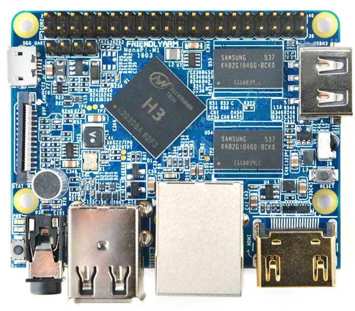
The NanoPi M1 uses the Allwinner H3 Soc. It integrates Ethernet, IR receiver, video/audio output and supports HDMI and AV-OUT.
It can be powered via the MicroUSB port. In such a small board it still integrates rich interfaces and ports.
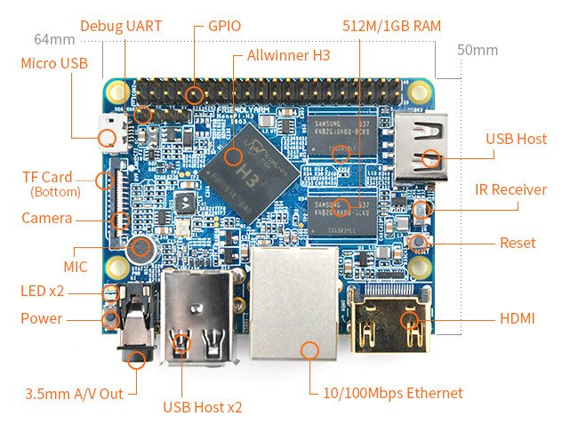
Besides the popular HDMI, Ethernet, USB-Host, USB-OTG, DVP camera interface and AVOUT (audio and video) it has an onboard Microphone, IR receiver, a serial debug port and a Raspberry Pi compatible 40 pin GPIO pin header.

NanoPi-M2 board specifications :
- SoC – Allwinner H3 quad core Cortex A7 @ 1.2 GHz with an ARM Mali-400MP2 GPU up to 600 MHz
- System Memory – 512 MB DDR3 (1GB as option)
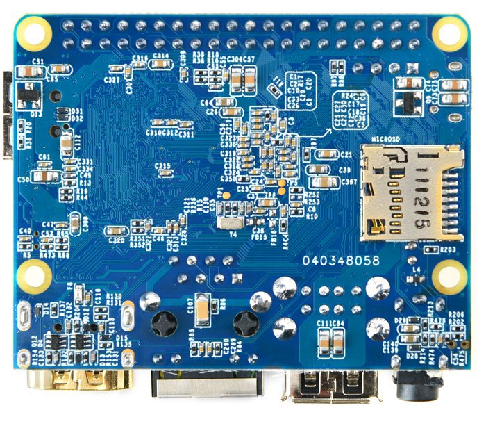
- Storage – micro SD card slot
- Video & Audio Output – HDMI and 3.5mm jack for CVBS (composite + stereo audio)
- Connectivity -10/100M Ethernet
- USB – 3x USB 2.0 host ports, 1x micro USB OTG port
- Camera – DVP Interface
- Expansions – 40-pin Raspberry Pi compatible header with UART, SPI, I2C, PWM, GPIOs, etc…
- Debugging – 4-pin header for serial console
- Misc – Power and reset buttons; 2x LEDs; IR receiver; on-board microphone.
- Power Supply – 5V/2A via micro USB port; 4.7V ~ 5.6V via VDD pin on “Raspberry Pi” header.
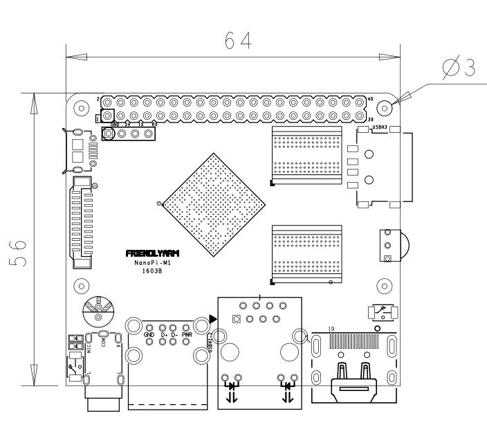
- Dimensions – 64 x 50mm (Orange Pi One dimensions: 69mm × 48mm)


SPECIFICATIONS
|
GPIO Pin Spec
| Pin# | Name | Pin# | Name |
| 1 | SYS_3.3V | 2 | VDD_5V |
| 3 | I2C0_SDA | 4 | VDD_5V |
| 5 | I2C0_SCL | 6 | GND |
| 7 | GPIOG11 | 8 | UART1_TX/GPIOG6 |
| 9 | GND | 10 | UART1_RX/GPIOG7 |
| 11 | UART2_TX/GPIOA0 | 12 | PWM1/GPIOA6 |
| 13 | UART2_RTS/GPIOA2 | 14 | GND |
| 15 | UART2_CTS/GPIOA3 | 16 | UART1_RTS/GPIOG8 |
| 17 | SYS_3.3V | 18 | UART1_CTS/GPIOG9 |
| 19 | SPI0_MOSI/GPIOC0 | 20 | GND |
| 21 | SIP0_MISO/GPIOC1 | 22 | UART2_RX/GPIOA1 |
| 23 | SPI0_CLK/GPIOC29 | 24 | SPI0_CS/GPIOC3 |
| 25 | GND | 26 | SPDIF-OUT/GPIOA17 |
| 27 | I2C1_SDA/GPIOA19 | 28 | I2C1_SCL/GPIOA18 |
| 29 | GPIOA20 | 30 | GND |
| 31 | GGPIOA21 | 32 | GPIOA7 |
| 33 | GPIOA8 | 34 | GND |
| 35 | UART3_CTS/SPI1_MISO/GPIOA16 | 36 | UART3_TX/SPI1_CS/GPIOA13 |
| 37 | GPIOA9 | 38 | UART3_RTS/SPI1_MOSI/GPIOA15 |
| 39 | GND | 40 | UART3_RX/SPI1_CLK/GPIOA14 |
DVP Camera IF Pin Spec
| Pin# | Name | Description |
| 1, 2 | SYS_3.3V | 3.3V power output, to camera modules |
| 7,9,13,15,24 | GND | Gound, 0V |
| 3 | I2C2_SCL | I2C Clock Signal |
| 4 | I2C2_SDA | I2C Data Signal |
| 5 | GPIOE15 | Regular GPIO, control signals output to camera modules |
| 6 | GPIOE14 | Regular GPIO, control signals output to camera modules |
| 8 | MCLK | Clock signals output to camera modules |
| 10 | NC | Not Connected |
| 11 | VSYNC | vertical synchronization to CPU from camera modules |
| 12 | HREF/HSYNC | HREF/HSYNC signal to CPU from camera modules |
| 14 | PCLK | PCLK signal to CPU from camera modules |
| 16-23 | Data bit7-0 | data signals |


Reviews
There are no reviews yet.